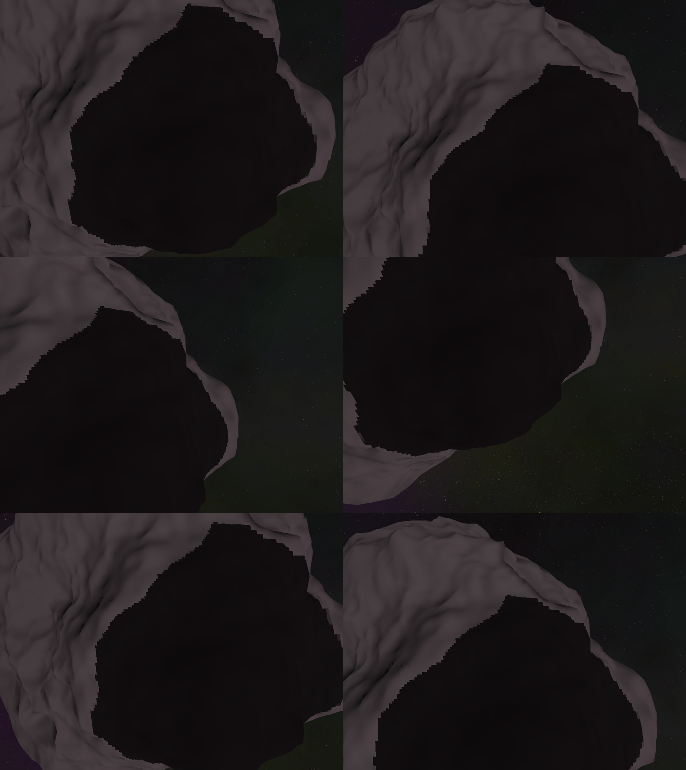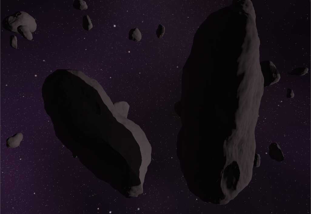
Creating a procedurally generated universe, one algorithm at a time.

Shadow of a doubt - part 2

Posted on Nov 22, 2020 graphics programming

In part 1 I mentioned the problem of shadow stability when using cascading shadow maps, or really any shadow mapping solution where the shadow map moves along with the camera frustum. I didn’t really go into detail with the solution though & since its fairly involved I thought I’d follow up with a more detailed explanation.

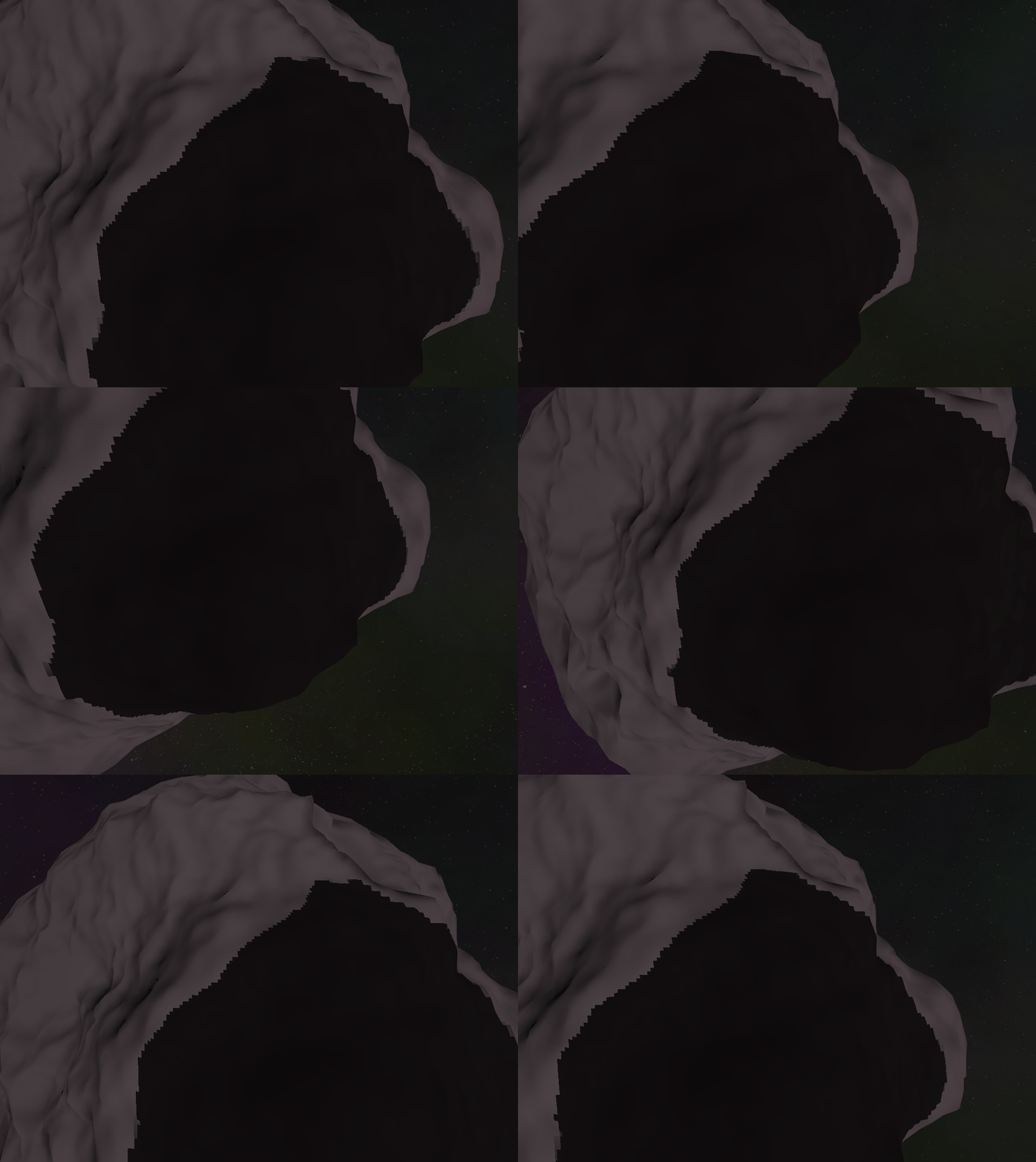
The instability of shadows happens because the shadow map has limited resolution & when the frustum moves slightly it can result in pixels being quantized into different parts of the shadow map that may have a different visibility state than on the previous frame. You can see this below where I’ve reduced the resolution of the shadow map and removed all PCF filtering. You can clearly see the edge of the shadow moving as the camera moves. This effect is pretty distracting and ugly - so lets fix it!

Unstable shadows that move along with the camera frustum

Unstable shadows

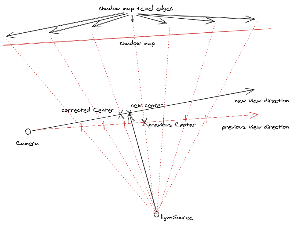
The way we do this is shown in the diagram below. Essentially we need to correct the position of all cascade shadow map frustums so that the frustum center is always fixed to a texel boundary from the previous frame. We perform this correction on every frame so that the frustum center snaps from boundary to boundary as the camera view vector moves. Doing this ensures that the texel boundaries on the current shadow map line up with the texel boundaries from the previous frames shadow map & eliminates the possibility of pixels for the same world space point being quantized differently by the two shadow maps.

Texel snapping

You might have noticed that for a perspective shadow map in the diagram above the texel sizes are non-uniform and get larger as you get to the edge of the frustum. This is correct, so its possible for quantization errors to be introduced particularly near the edges of the screen. If you really want to have pixel perfect shadows you’d need to move to a uniform orthographic projection, though in my case orthographic projection doesn’t work well for a central point light source like a solar system. As you can see below, once the correction is applied the shadow looks almost completely stable and any minor movement is pretty much unnoticeable (especially so once the shadow map resolution is increased and PCF filtering applied).

Stable shadows by snapping frustum movement to shadow map texel positions

Stable shadows

I’ve extracted the approximate code I use to do this center correction below. The way it works is to project the new center using the previous view-projection matrix, which transforms the x & y coordinates to positions on the shadow map. We then round those x & y coordinates to the nearest texel boundary, then run the projection in reverse (using the inverse of the view-projection matrix) to convert the corrected center back into world space.

constexpr float TexelScale = 2.0f / 1024; // shadow map resolution of 1024px
constexpr float InvTexelScale = 1.0f / TexelScale;

// project the new center using the previous projection & snap its
// position to a whole texel value, before re-projecting back into world
// space
const XMVECTOR projectedCenter = XMVector4Transform(
  XMVectorSetW(center, 1.0f), cascadeViewProjection);
const float w = XMVectorGetW(projectedCenter);
const float x = floor((XMVectorGetX(projectedCenter) / w) *
  InvTexelScale) * TexelScale;
const float y = floor((XMVectorGetY(projectedCenter) / w) *
  InvTexelScale) * TexelScale;
const float z = XMVectorGetZ(projectedCenter) / w;
XMVECTOR correctedCenter = XMVector4Transform(
  XMVectorSet(x, y, z, 1.0f),
  XMMatrixInverse(nullptr, cascadeViewProjection));
center =
  XMVectorScale(correctedCenter, 1.0f / XMVectorGetW(correctedCenter));

Shadow of a doubt - part 1

Posted on Nov 21, 2020 graphics programming

shadows close up

You might think that realtime shadows are a largely solved problem. Most games have them, and for the most part they look great - but this hides the fact that aside from some recent advances in realtime ray-tracing (RTX etc.) the state of the art for realtime shadown rendering is an ingenious, but in practical terms terribly flawed technique known as the shadow map. I knew eventually I’d have to build in shadowing support into my engine, but what I didn’t realize was that shadow mapping techniques are really optimized for usecases where your viewpoint is close to a solid ground plain with a directional lightsource projecting down from above. Space represents a really challenging environment as you don’t have any ground plain, you have a point light source (a star) - not a directional one, and there are potentially huge distances between shadow casters and shadow receivers.

The basics of how shadow mapping works is shown in the diagram below. You render the scene twice, once from the perspective of the light source, and then once from the player camera. Each rendering of the scene records the distance from the source to the nearest piece of geometry, otherwise known as a depth map. Once these two depth maps have been calculated, we can determine which parts of the scene are lit or shadowed by calculating whether the distance from the lightsource at any given point is greater than or equal to the depth in the lightsources depth map for that given point. In the example below, point A is lit because the distance along the ray from the light is equal to the distance in the depth map, but B is in shadow because the distance along the ray from the light is greater than the distance in the depth map.
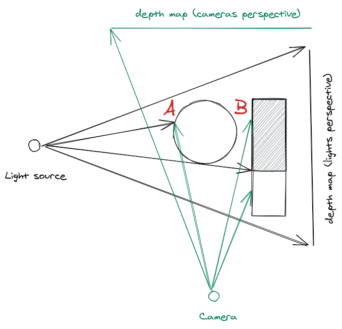
Shadow map basics

Soft shadows

The problem with classic shadow maps is that they cast hard edged shadows, and the accuracy of the shadows is dependent on the resolution of the shadow map, so over time a number of techniques have been developed to try and achieve higher quality and more natural looking shadows.

VSM - Variance shadow maps: These produce really bad ‘haloing’ or light-bleeding artifacts when you have overlapping shadow casters. In a crowded asteroid field, you frequently have more than one asteroid blocking a light source, so this is a non-starter.

ESM - Exponential shadow maps: These have some nasty edge cases that as long as you have a ground plain and don’t have too many overlapping shadow casters you probably wouldn’t notice. In a space asteroid field, these assumptions are false much more often leading to frequent unsightly artifacts (see the image below for an example)
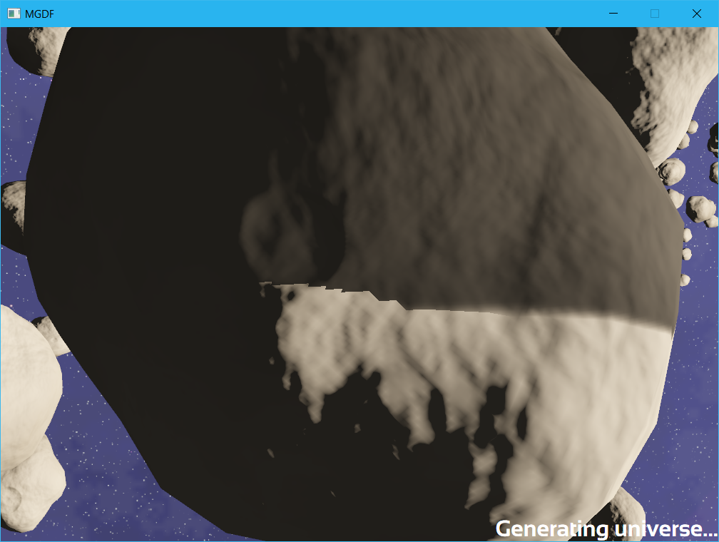
ESM artifacts

PCF - Percentage closer filtering: A brute force technique to just take multiple samples around a pixel and average the results to smooth out the edge of the shadows. While its not very elegant, its simple and gets the job done so thats what I ended up using

Shadow map resolution

The next problem you run into is that since shadow mapping is a screen space technique, the shadow map has a finite resolution, so you end up having to balance between the resolution of shadows & the draw distance of those shadows as the map has a limited amount of world space that it can cover and for a larger worldspace target, each pixel in the shadow map needs to cover a larger area leading to pixellated shadows. This is where most of the tweaking and hacks around effective use of shadow maps comes from - optimizing the space in the shadow map so that you get the best resolution for shadows close to the camera combined with an acceptable shadow draw distance.

Directional vs point lights

As I mentioned - most uses of shadow maps involve directional lights. The reason for this is that you can use an orthographic projection to render the shadow depth map, which results in a nice uniform resolution of the shadow depth map. Using a point light involves having to do a perspective projection of the depth map that results in higher resolution of shadow samples toward the center of the shadow map. Unfortunately in the kind of space environment I want to render we have a point light i.e. a star in the center of the solar system, so we have to use a perspective projection. Now to be totally accurate you would need to do a cubemap projection and get a depthmap from the stars position covering all possible viewer positions, but this is impractical as the shadow resolution would end up being far to low & you’d be rendering depth maps for objects that are so far from the viewer as to be non-visible anyway. So in order to increase the shadow map resolution to practical levels we cheat by only recording the depth map that lies within the visible area of the screen - known as the camera frustum.
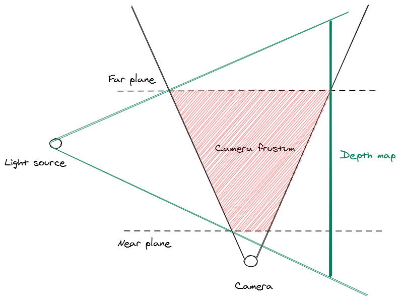
Setting the depth map to the view frustum

This gives us the best use of our available shadow map space as we’re only rendering depth values for the area that covers the visible screen - however, even in this case the limited resolution of the shadow map means that up-close shadows still look very blocky. To fix this we can rely on another brute-force technique - known as cascading shadow maps (CSM). Just render a bunch of depth maps starting from a small one close to the camera and expanding in size along the view vector, then when rendering the shadows, pick the shadow depth samples from the highest available depth map at that point in the view space.
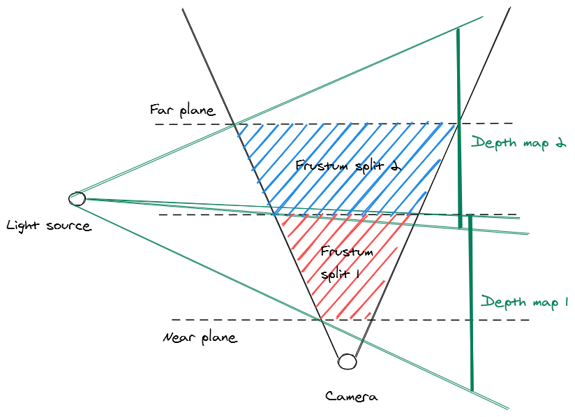
Splitting up the frustum into multiple depth maps

Because each cascade overlaps the others, we can get a bit of extra resolution by not partitioning strictly by the distance along the view vector, but by checking if the world space position hits a position that the depth map covered - that way we can aggressively prioritize using the closer & therefore more detailed shadow maps. Below is a comparison of which cascade gets picked (warm colors represent the highest detail cascades, & cooler colors represent lower detail cascades) under the two approaches.

Cascade strict distance vs aggressive
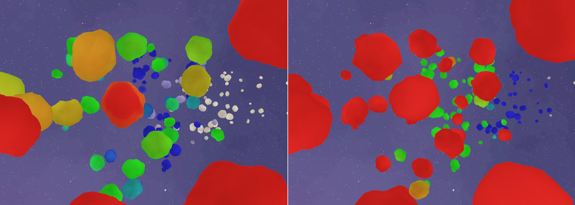
Cascade picking comparison

Theres also some art to picking how to split the cascades & how many to do - I use a logarithmic distribution, favoring more maps closer to the camera for better up close resolution at the expense of less detail further away & found 6 cascades to be a good balance between quality and performance. Below we can see an animation of the algorithm in action, picking different cascades as the camera moves through the scene.
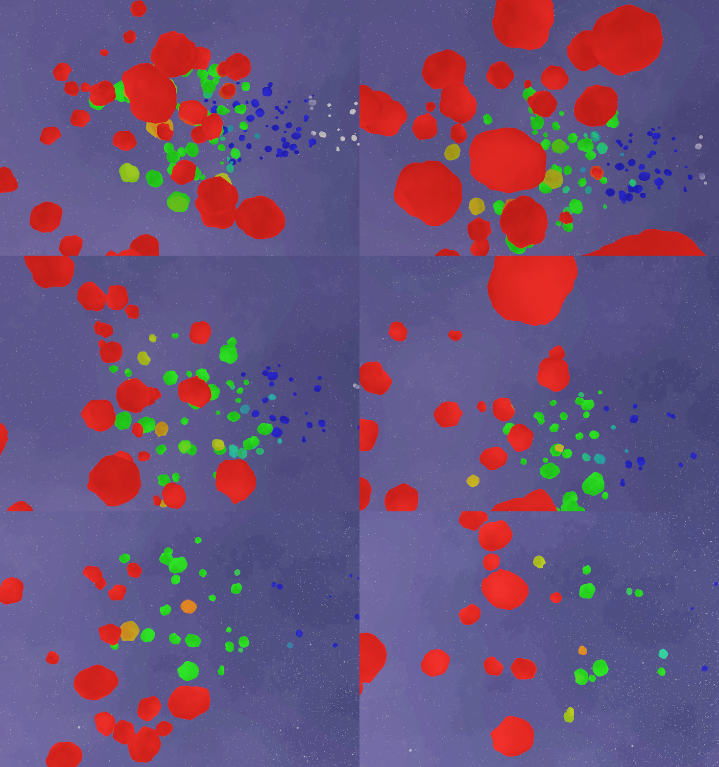
Cascade picking in action

Theres also another problem that this introduces, since the depth map is constantly moving along with the camera view, the shadows can appear to move or ‘swim’ when you move the camera. For this you have to go to some considerable lengths to ‘snap’ movement in the depth map vectors to whole texel multiples (i.e. you need to calculate the world space size of a texel at the point of the view vector and only allow the depth map source to move in increments of that - this doesn’t completely remove shadow movement (as perspective depth maps have non-linear texel sizes, but it keeps things largely stable in the center of the viewport).

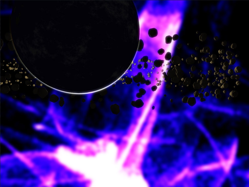
One nice thing about the shadow map is that is can be used just as easily for shadowing geometry as for volumetrics or particles. Shown below are shadows cast by asteroids onto volumetric fog used for planetary rings.
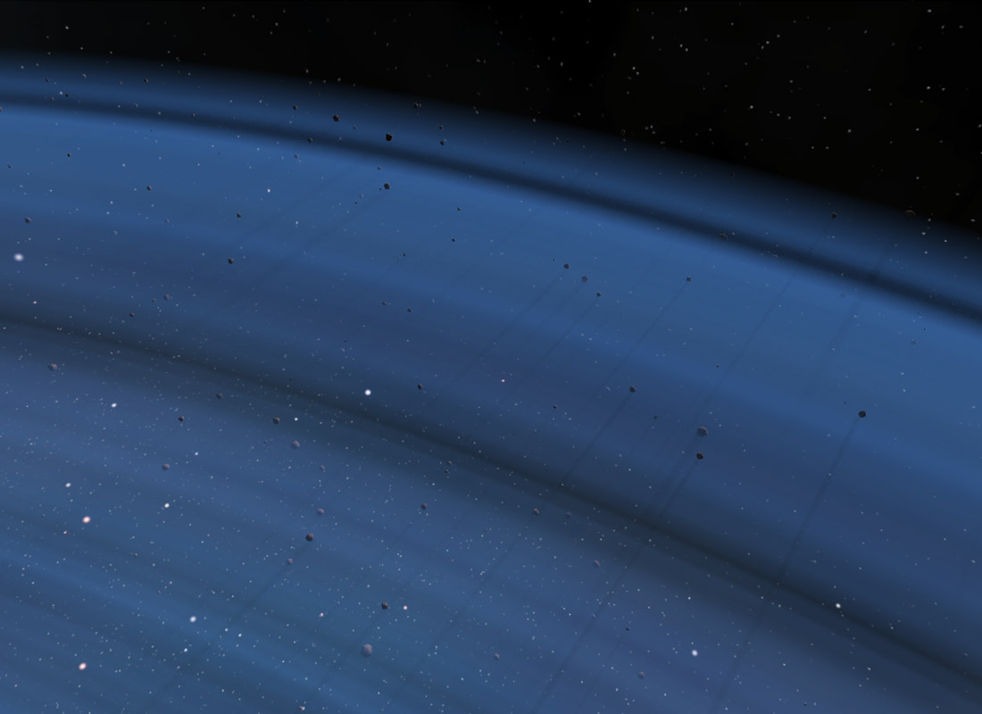
volumetric shadows

Geometric analytical shadows

All the hacks above get us to a point where we get pretty nice looking dynamic shadows for objects up close, but as things get further away the lower resolution of the shadow map makes them less and less effective. This is a problem in space scenes where there is typically very large distances involved and we don’t really want shadows from small objects like asteroids projecting gigantic shadows onto planets half way across the solar system. To solve this I decided to treat very large and very small objects as separate as far as the lighting and shadowing was concerned. And because the large objects have very predictable geometry I could come up with some very geometry specific shadowing techniques that allow for much better results than a generic technique like shadow mapping.

All planets are spheres & its mathematically relatively simple to do a vector sphere intersection test so you can analytically determine if any planet is in the shadow of any other planet. You can also determine the distance of the intersection from the center of the shadow caster sphere to the edge & can therefore trivially do soft shadows from any given planet to another.
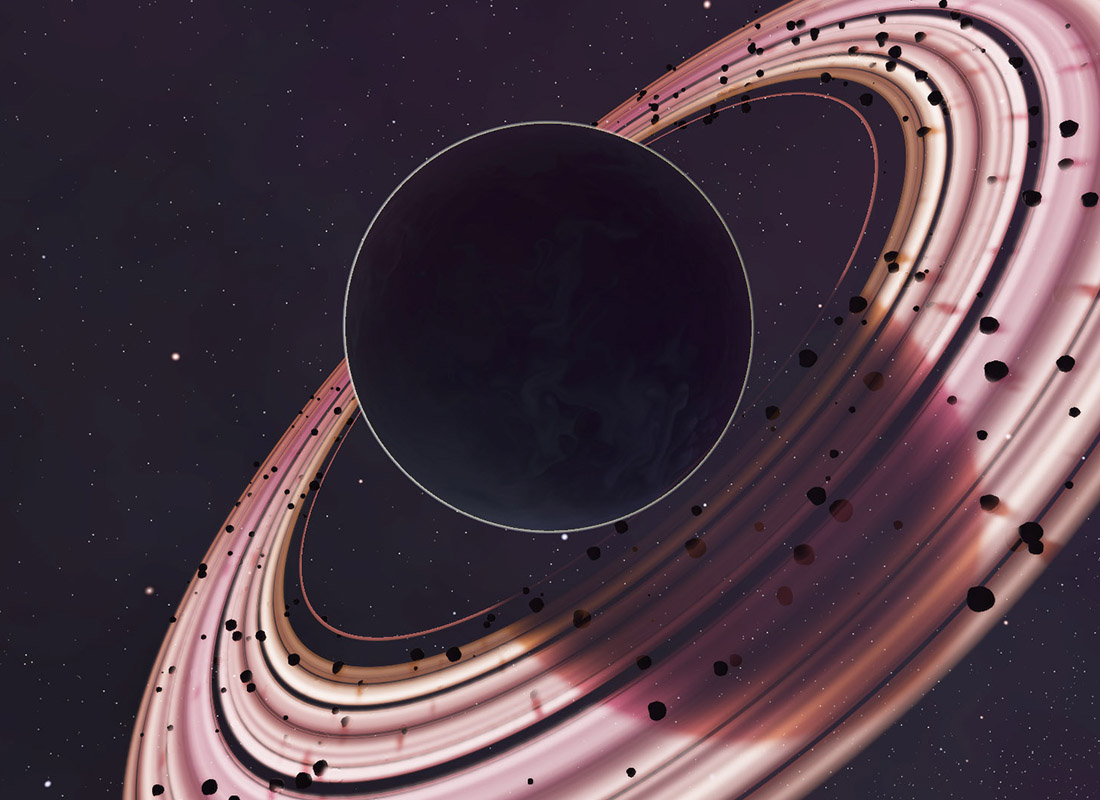
Geometric shadow

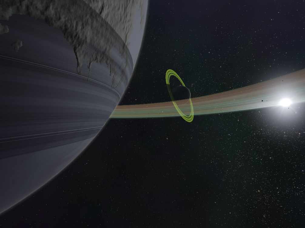
Similarly the shadows on a planetary ring system can be determined with some basic geometry. In that case you want to see if the vector at any point in the ring plane passes through the planet sphere or not. Finally you can also cast shadows from the ring plane down onto the planet itself by doing a plane intersection test from a point on the planet sphere through to the lightsource, determine the radius of the intersection from the origin & then lookup the ring texture to see the alpha value of the ring at that point.
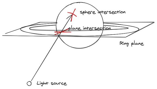
ring shadow geometry

projected ring shadows

Combined these effects allow for a pretty convincing solution to the shadowing problems I’ve run into thus far, but the lesson here is that there isn’t really a good general case solution when using shadow maps, you’ll need to hack and tweak them (a lot) to get good results.

One unrelated thing I wanted to note: you might have seen it was 4 years since the last post. I have actually been working on Junkship during this time, just procrastinating to an insane degree when it came to writing posts. I tend to update more often with screenshots and videos on Twitter & have dabbled in streaming on Twitch, but I have a huge backlog of topics I’d like to write detailed posts on & I’m hoping that finally getting this published can help me get back into the rythm of writing more often. But who knows maybe it’ll be another 4 years :)
Jupiter Jazz

Posted on Jun 9, 2016 graphics programming directx proceduralcontent

image

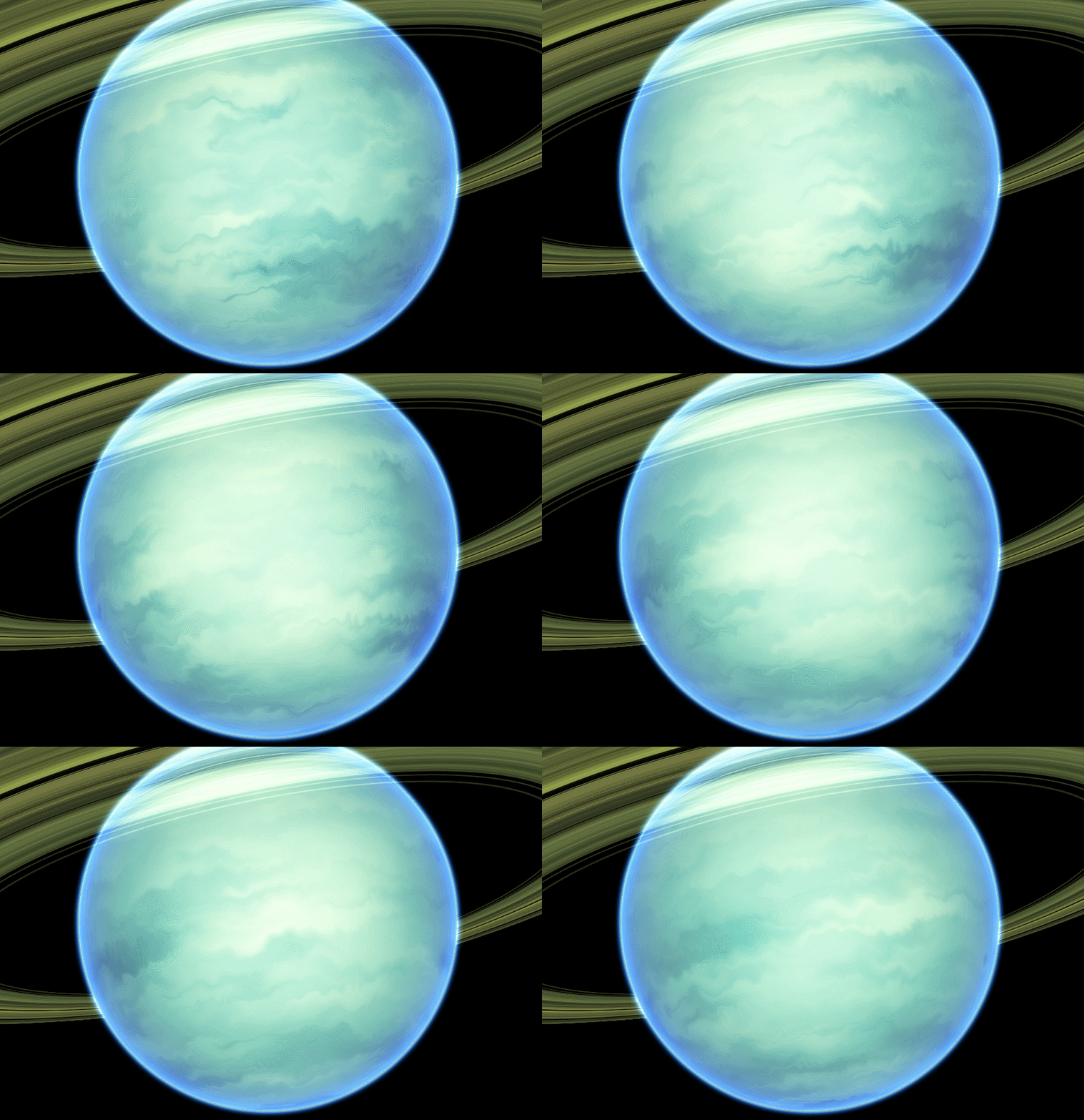
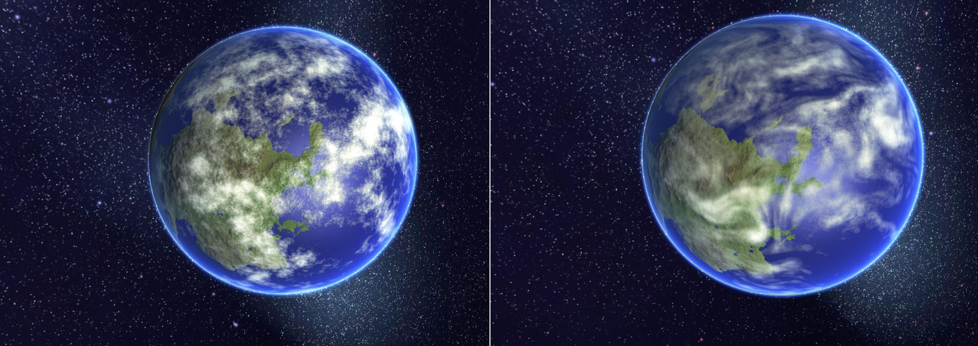
One of the main areas where I was never satisfied with Junkships procedural planetary generation was the generation of convincing looking gas giants and cloud systems on earthlike planets. I got some initially passable results by tweaking simplex noise, and adding some approximations of vortices as described here, but it never looked that great due to the fact that cloud formation is a highly physical process involving wind, temperature, pressure, and a bunch of other phenomena rooted in pysical simulation.

It was always my plan to revisit this part of the system and to add some amount of fluid simulation when generating cloud layers. With that said, my goal was not to accurately model the actual physics, but to build a lightweight simulation that would give a good final result, and run fast.

After reading up on the current state of the art I came across a great article here which proposed a really simple method that looked like it should tick all the boxes I was looking for. While this proved to be broadly true, there were however a number of isssues I had to overcome in order to get a satisfactory solution.

The TL;DR of the technique is that you generate a heightmap using a noise function (in my case simplex noise), calculate a vector which is the gradient of the noise field at each point, then rotate that vector 90 degrees around an axis defined by the normal. This set of rotated normals is your ‘flow map’. You then take your input texture and your flow map and move every texel in the input by the vector in the matching texel of the flow map - if you do this repeatedly the input texture looks as if it is a fluid flowing according to the hills and valleys in the original height map.

There is at least one other implementation of this technique out there (Heres some good slides by the developer of Space Nerds In Space) but I haven’t seen any that use the GPU to do the work. The advantage of using the GPU is that computing the flow calculations for a texture can be done dozens of times per second as opposed to minutes per texture iteration with CPU based implementations. This means that its possible on a mid range PC to generate gas giants or cloud layers within a second or two which is in keeping with my goal of having all asset generation occur near instantaneously at runtime.

There were a few problems with the technique as presented in the original paper, the main one being that it is designed to work in 2 dimensions, whereas I needed to generate the flow map on the surface of a sphere. While ‘rotating’ a vector by 90 degrees in two dimensions is pretty trivial, its not so obvious what this means in 3 dimensions. For those whose linear algebra is a little rusty the solution is:

  • calculate the normal at the position on the sphere
  • calculate the tangent at the position on the sphere (you could also use the binormal/bitangent instead)
  • calculate the normal from the heightmap at the same position on the sphere
  • calculate the cross product of the tangent and heightmap normals

or in HLSL

float3 flowVector = cross(input.tangent,heightmapNormal);

This generates a flowmap with a smooth contour of vectors that can be stored in the rgb components of a texture as shown below.

image

The second problem with the technique is that it is effectively like putting the input texture into a blender, if you run enough iterations, all the original input colors will become evenly distributed and blended together. Because of this, its important to ensure that there is a limited number of flow iterations in order to allow for some mixing - but not too much. The problem with this is that the animation of the flow process looks really cool and it would be a pity to have to use a static version of a texture which is supposed to be showing cloud systems which should change appearance over time.

My solution to this was to split things into 2 stages - the first is the iterative blending process where each output texture is then recombined with the flow map. Once a number of iterations have been run. Once this has been done we have an input texture that can be used as the input to the second stage.

The second stage still involves the use of the flow map to warp the input texture, but importantly the output is not used as the input to the next frame (to prevent excessive mixing over time). Instead, the same input texture is used on each frame, and the flow map is rotated by a fixed amount. This gives the appearance of some dynamic fluidity when rendering, but ensures that the appearance of the texture remains consistent over long periods of time.

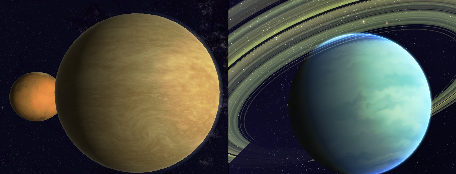
Gas giants: Old technique vs New technique

image

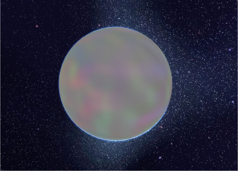
Clouds: Old technique vs New technique

image

As you can see the new technique gives vastly superior results to what I was doing before, ands its also proven to be much easier to tweak the generation parameters to provide a more predictable range of good outputs.

In other news I am also planning on fully open sourcing the Junkship solar system generation codebase soon. There are a couple of reasons for this, the main one being that I no longer have any desires to build this out into a fully fledged game or otherwise commercial product, I’d much prefer to refocus it into what it is, which is a cool demo for procedural graphics techniques. Because of this there is no real need or advantage to keeping the code private anymore, I’d much prefer to share and see other game developers take advantage of and build upon the the stuff I’ve worked on. Theres a fair chunk of work that still needs to be done to tidy things up and finish off some of the generation code, particularly around lighting and color palette generation - but I’m hoping to get the code up on Github in the near future (Take that with a grain of salt though, my time estimates tend to run on something approximating Valve Time)

My god its full of stars

Posted on Feb 2, 2014 graphics programming directx proceduralcontent

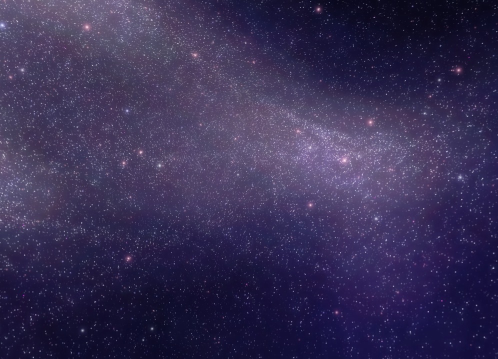
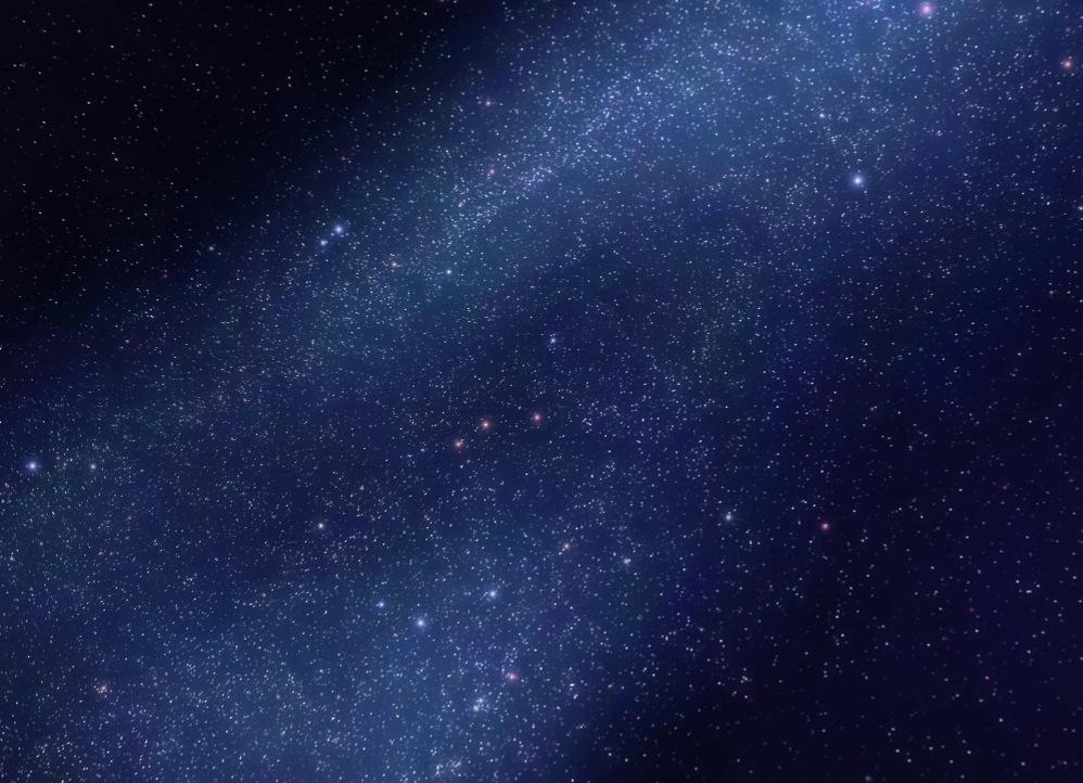
It has been a long time since I last worked on generating procedural star fields, but I was never particularly happy with the result that I came up with in my first attempt so when some time presented itself I decided to revisit the problem to see if I could come up with a better solution. It turns out I could, below is an example of what I came up with.

image

My original method (shown below) was largely based on combining successive layers of Perlin noise, and while this worked ok for the actual stars themselves it usually looked pretty terrible when it came to rendering nebulas and the gas and dust surrounding dense clusters of stars.

10-11-2011

The reason for this is that star and galaxy formation is an inherently physical process, shaped by the gravitational interactions of billions of stars and giant clouds of gas and dust. The Perlin noise approach failed to take any of these physical factors into account and as a result it was extremely difficult to tweak it to get the relationship between star and gas density correct, and to get the overall shape and structure of nebulas looking convincing.

Because of this it seemed obvious that in order to get this right I was going to have to implement some sort of physics based particle system to at least approximate the physics involved. With this in mind I realized that given the number of particles that would have to be simulated (probably millions) that this was going to be impractical to do on the CPU and was going to be a job for the GPU if I wanted to keep the generation time to a minimum.

I ended up writing a Compute shader in which a large number of particles are simultaneously attracted to a handful of attractor particles which move randomly about 3d space. These attractor points are repositioned each frame on the CPU (as there’s only 2 – 3 of them ) and fed into the shader as a buffer. The shader then calculates the acceleration acceleration caused by each particle due the force of each attractor ( proportional to the square of its distance between the attractor and particle ) and updates the particles position.

The effect of this is a very loose approximation to the force of gravity, but where all the particles can move independently of each other, making it extremely parallelizable. Having multiple attractors is essential in such a simple simulation as having a single attractor results in all particles converging toward a single point, whereas having particles being under the influences of multiple concurrent forces creates interesting and unpredictable patterns. Below is an early rendering showing around 1 million particles being simulated and rendered as point sprites.

7-12-2013

Here’s the source code for the compute shader

cbuffer Constants  : register(cb0)
{
    uint GroupDimX;
    uint GroupDimY;
    uint MaxParticles;
};

cbuffer Physics : register(cb1) 
{
    float FrameTime;
    uint AttractorCount;
};

struct Particle {
    float3 CurrentPosition;
    float3 OldPosition;
    float3 Velocity;
    float Scale;
};

struct Attractor {
    float3 Position;
    float3 Destination;
    float Velocity;
    float Strength;
    float MinAttractorDistance;
};

RWStructuredBuffer<Particle> srcParticleBuffer : register(u0);
StructuredBuffer<Attractor> attractorsBuffer : register(t0);

[numthreads(1024, 1, 1)]
void main( uint3 dispatchId : SV_DispatchThreadID )
{
    uint id = dispatchId.x + ( GroupDimX * 1024 * dispatchId.y ) 
        + ( GroupDimX * GroupDimY * 1024 * dispatchId.z );

    //Every thread renders a particle.
    //If there are more threads than particles then stop here.
    if(id < MaxParticles){
        Particle p = srcParticleBuffer[id];
        float3 a = float3(0.0f,0.0f,0.0f);

        for (uint i=0;i<AttractorCount;++i) {
            float3 diff = attractorsBuffer[i].Position - p.CurrentPosition;
            float distance = length( diff );

            if ( distance < 
                    attractorsBuffer[i].MinAttractorDistance ) {
                // make sure particles don't appear inside an 
                // attractors min distance. If a particle
                // gets inside the min distance, we'll push it 
                // to the opposite side of the min sphere
                // This reduces large numbers of particles
                // converging in a point around an attractor

                float3 push = diff + 
                    normalize( diff ) 
                    * attractorsBuffer[i].MinAttractorDistance;
                p.OldPosition += push;
                p.CurrentPosition += push;
            }

            a += ( diff * attractorsBuffer[i].Strength ) 
                / (distance * distance);
        }
        float3 tempPos = 2.0*p.CurrentPosition 
            - p.OldPosition + a*FrameTime*FrameTime;

        p.OldPosition = p.CurrentPosition;
        p.CurrentPosition = tempPos;
        p.Velocity = p.CurrentPosition - p.OldPosition;

        srcParticleBuffer[id] = p;
    }
}

The particle simulation when suitably tweaked came up with all sorts of interesting looking nebula type clouds, and worked well for rendering fields of stars. However as you can see in the screenshot above, even with a lot of blur applied to the particles, when rendering a cloud of point sprites they had kind of a lumpy appearance that gave away the fact that the cloud was actually composed of a finite number of particles. I tried all sorts of variations of increased blur, low pass filters, different particle sizes and shapes but the lumpiness was always present to some degree

It took me quite a while to figure out a solution for how to smooth out the particle field and I eventually figured it out after remembering an article I read about the rendering technique used to draw the skyboxes in Homeworld 2 (http://simonschreibt.de/gat/homeworld-2-backgrounds/). In that game the backgrounds were all vertex shaded using actual geometry which gave the backgrounds a very smooth almost painted look.

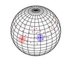
This got me thinking, could I use vertex shading to try and smooth out the rendered cloud? I started by normalizing all the particle positions so they sat somewhere on a bounding sphere with a radius of 1 unit. Then for each vertex on that sphere I summed up the number of particles within a certain distance and recorded that as the particle density at that vertex.

vis

For example, in this image we can see that the vertex at the center of the red circle has a density of 1 as there is only one particle within the circles radius, whereas the blue vertex has a density of 4 as there are 4 nearby particles

The pixel shader can then render color based on this density, which the graphics card hardware will interpolate for us between the respective vertices for a smooth continuous output. Throwing all these ideas together gave me the following vertex shader (the pixel shader is trivial, it just renders a color whose opacity is based on the vertex.Intensity value and uses the normalized vertex.Velocity vector to lerp between two possible color values )

cbuffer ParamsBuffer: register(cb0)
{
    float4x4 WorldViewProjection;
    float MaxDistance;
    int MinThreshold;
    int ParticleCount;
};

StructuredBuffer<Particle> particleBuffer : register(u0);

Nebula_VSOutput main(VSInput input)
{
    Nebula_VSOutput output;

    float4 worldPosition = mul(float4(input.Position,1.0f), 
            WorldViewProjection);
    output.LocalPosition = input.Position;
    output.Position = worldPosition.xyww;
    output.Velocity = float3( 0.0f, 0.0f, 0.0f );

    int intensity = 0;
    // find how many particles are within a threshold distance
    // of this vertex
    for (int i = 0; i < ParticleCount; i++)
    {
        Particle p = particleBuffer[i];
        float distance = length( normalize( p.CurrentPosition ) 
                - input.Position );
        intensity += distance <= MaxDistance ? 1 : 0;
        output.Velocity += p.Velocity;
    }

    output.Velocity = normalize( output.Velocity );
    output.Intensity = saturate( ( intensity - MinThreshold ) 
            / (float)ParticleCount );

    return output;
}

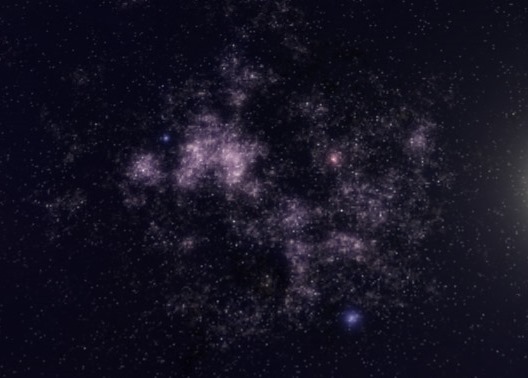
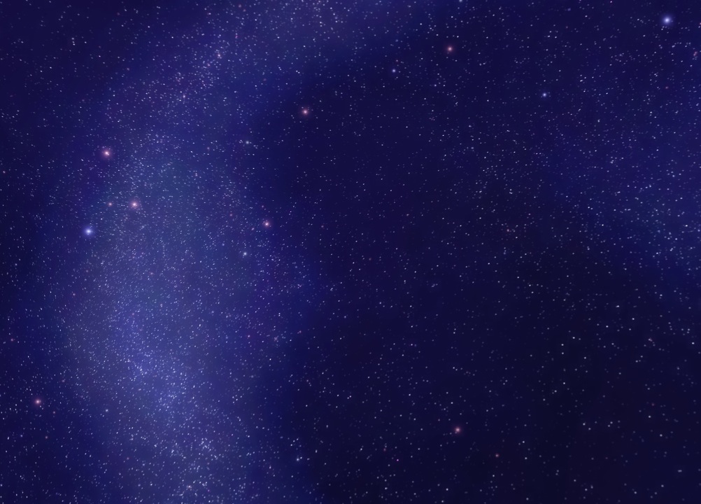
Turns out it worked exactly as I had hoped! the rendered clouds were now perfectly smooth provided that the sphere used to render the skybox had a sufficient polygon count. It also had the ancillary benefit of requiring far less particles for an equivalently detailed cloud which helped reduce the simulation time. Below are a couple of different procedural star field renderings, each field is rendered after around 60 physics iterations and contains around 2 million particles for the point sprite stars, and around fifty thousand particles for the nebula clouds. A full skybox is rendered in 300 layers with one layer per frame ( so as to not adversely affect the frame rate of other rendering ) which ends up taking around 5 seconds.

image

image

How to properly distribute DirectX in an installer

Posted on Nov 6, 2012 programming directx

I see threads all the time where people complain about game installers that have DirectX install wizards that pop up mid install, or about the size of the end user redistributable bloating their game installer. I understand why this is a problem, there’s lots of advice and documentation telling you what NOT to do when distributing DirectX (Don’t just include the dlls in your install folder!), but not much in the way of what you SHOULD do. So after seeing another iteration of this discussion on this recent Reddit thread, I decided I’d write this post so that those who are unsure of how to redistribute DirectX in their own games installer will be able to get it right (BTW - the installer in the linked thread is doing it wrong despite the thread title).

Step 1 – Create a minimal installation package

Most Windows installs already have DirectX installed by default, Windows XP SP2+ includes DirectX 9.0c, Windows Vista includes DirectX 9&10 (and SP2 includes DirectX 11), and Windows 7 includes 9,10&11 right out of the box. So really all you have to do to ensure that all prerequisites are installed correctly is to ensure that any dll’s you use that are part of the DirectX SDK and NOT part of the core DirectX install are installed.

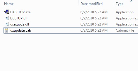
The first step in doing this is to go to the DirectX SDK install directory (usually something like “C:\Program Files (x86)\Microsoft DirectX SDK (June 2010)”) and go into the Redist folder. Create a new folder somewhere else on disk and copy the following files from the Redist folder into it

  • DXSetup.exe
  • DSETUP.dll
  • dsetup32.dll
  • dxupdate.cab

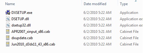
You should now have a folder that looks something like the following

image

Step 2 – Determine what D3D libraries you are using

Now you need to find what D3D libraries your solution is actually using. If you’re not sure (and your using c++) In Visual Studio, go to project properties and you probably have these listed under the ‘Additional Dependencies’ field in the Linker->Input window. Take note of any .lib files starting with d or x (e.g. xinput.lib or d3dx9.lib).

Now go back to the DirectX SDK Redist folder and for each lib you identified, grab the most recent copy of the corresponding .cab file. For example, if you are using d3dx9.lib, then (assuming you are using the June 2010 SDK) you would grab Jun2010_d3dx9_43_x86.cab (also assuming your game is compiled as a 32 bit application – if not, go with the x64 versions of the same .cab). Similarly if you were using xinput.lib, you would grab APR2007_xinput_x86.cab. Copy all the selected .cab files across to your install package folder we created in the previous step.

You should now have a folder that looks something like the following

image

Step 3 – Bundle these files in your installer and execute DXSETUP silently

The files you identified above are all that are required to install the DirectX prerequisites on any users machine. Note how its only a fraction of the size of the full end user redistributable. Now make sure to include all those files in your installer, then at install time, extract them to a temp folder and run DXSETUP.exe with the /silent argument like so

dxsetup.exe /silent

It is critical that you use the /silent argument as this prevents the DirectX installer UI popping up during your own install. Don’t worry if the user already has the prerequisites, the dxsetup program is smart enough to not install anything that is already installed.

Here’s an example from Junkship’s nsis installer script which does the DirectX install

;--------------------------------
; install directx11 update
Section "Install Directx 11 June 2010 update"

    SetOutPath $TEMP\Junkship
    File dxredist\*.cab
    File dxredist\*.dll
    File dxredist\DXSETUP.exe

    ExecWait '"$TEMP\Junkship\dxsetup.exe" /silent'
    SetOutPath $TEMP
    RMDIR /r $TEMP\Junkship\dxredist
SectionEnd

Step 4 – Profit!

That’s it! (though if you are using DirectX 11 and want to support windows Vista users, you may need to do some additional prerequisite checking as detailed in this article)

NOTE: Most of the information included from this post was sourced from this MSDN article if you want to know more